Rational & Eclipse UML2 Tools - Flawed UML Component Connections
Connecting UML Components with the Ball and Socket notation in Rational Software Modeler (RSM/RSA) and Eclipse UML2 Tools is not fully implemented or flawed. Too fully understand my point you have to keep in mind that these tools are for modeling, not just drawing a picture/diagram. Thus the internal model representation of what you diagram must be correct and complete.


The Need:
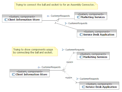
I discovered this issue while trying to design a suitable domain specific language/model for architects to talk about systems and what interfaces/data connections they had between them. The users understand components, so our systems were components. Additionally, interfaces at a high level make sense for being an "agreed upon" contract of interaction between systems. So, the components will realize the interfaces or <

If you look closely at the diagram you will note that the ball and socket do not really connect, which is the first indication that there is a problem. RSM will not let you connect the ball and socket visually or in the model. The Eclipse UML2 Tools will let you connect them, but it fails to model them correctly, though it is still in the early phases of open source development so it kind of gets a pass for most of this discussion.
UML Defines:
So what does UML say should be possible, both from a visual representation (syntax) and model structure (more semantics)? The UML specification 2.2 (Superstructure) says on pg 151 in section 8.1 at a high level that:
"As a result, components and subsystems can be flexibly reused and replaced byconnecting (“wiring”) them together via their provided and required interfaces....In addition, the BasicComponents package defines specialized connectors for ‘wiring’ components together based on interface compatibility."
The Assembly kind of Connector
At the syntax and semantics level however there are a few details to understand. The major construct to support "wiring" are Connectors. The ComponentBase extends the Connector definition allowing for two kinds of Component specific Connectors, Delegation and Assembly. Also, you "wire" both components and component parts/ports which can make the spec hard to read. It states on page 155 in section 8.3.3:
"The connector concept is extended in the Com ponents package to include interface based constraints and notation.A delegation connector is a connector that links the external contract of a component (as specified by its ports) to the internal realization of that behavior by the component’s parts. It represents the forwarding of signals (operation requests and events): a signal that arrives at a port that has a delegation connector to a part or to another port will be passed on to that target for handling.An assembly connector is a connector between two components that defines that one component provides the services that another component requires. An assembly connector is a connector that is defined from a required interface or port to a provided interface or port."
Notice that for assembly it does not say compo nent part, but components and uses the word between. To make things confusing the major examples (pg 153 Figure 8.15) are on Component Instances that are Parts, not between components so to be sure I also found the following on page 156 under constraints:
"[5] An assembly connector must only be defined from a required Interface or Ports to a provided Interface or Port."
An interesting note, but I will go no deeper is that the table 8.2 makes it sound like connecting the ball and socket by a usage/dependency would be equivalent, especially when you factor in
Figure 8.14. Table 8.2 from page 160:

So, the assembly connector defined in UML supports connecting the ball and socket between components, which should be reflected in the model as an Assembly kind of Connector.
Ecore/EMF Provides:
It turns out that the Ecore/EMF model of UML which Rational and Eclipse UML2 Tools leverage support the Assembly Connector per the UML spec. The below two figures show from Eclipse the construction of a component required interface connecting via an Assembly Connector to the same interface provided/realized by a component. The properties could be set and the selector filtered the options correctly given that the interface type had to match.


How Rational (RSM) FAILs gracefully:
In Rational you cannot even create an assembly connector between two components either visually or in the model. The diagram canvas will not allow you to select a component that is not an instance nor will it let you specify it when you are drawing a new (yet to be typed) line. In the model if you try to add a new relationship between two components it will not give you the assembly connector option.
Even worse if you try to connect the ball and socket in Rational with a use or depends you will actually be connecting the interface to itself, see below. Basically the ball and the socket are representations of the interface, not the provided or required ones.

Sadly, Rational provides the Assembly connector and even renders it fine when you are using instances of components (Parts) in the structural view inside a component. So, in my estimation the just mis-understood the specification or they did not keep up with the changes to UML as this was added as part of 2.0 from what I can tell.
A bug will be logged with IBM for the Rational Software Modeler (RSA/RSM) tools, and the ID/Link to it is TDB.

Comments